
by Bohuslav Bobrik Bohuslav Bobrik

Clamp-On Application for High Pressure Ethylene in EVA (Ethylene Vinyl Acetate) Production

APPLICATION NOTE
Petrochemical plant at dusk producing Ethylene Vinyl Acetate (EVA)

Clamp-On Application for High Pressure Ethylene in EVA (Ethylene Vinyl Acetate) Production

Summary

Jiangsu Sierbang Petrochemical Co. Ltd in China produces Ethylene Vinyl Acetate (EVA), a copolymer resin valued for its lightweight and excellent foamability. The process is part of a polyethylene plant and requires high-pressure ethylene from reciprocating compressors, with the flow rate on this line needing to be accurately measured to keep the EVA produced within specification — too low a flow rate leads to an incomplete reaction. With pressure inside the pipeline reaching up to 200 MPa, flow meters that require cutting the pipe were not a safe option. Uncertain that a clamp-on solution could deliver the required accuracy at such pressure, the customer requested a field demonstration from the Panametrics team.

FluidEthylene gas
Pipe121 mm x 35 mm (4¾” x 1.38″), Carbon Steel
Process Temperature20 °C (68 °F)
Process Pressure195 MPa (28,282 psi)
Fluid Sound Speed1,679 m/s
Panametrics

Benefits:

  • Low maintenance
  • No pressure drop
  • No interruption to operations
  • Safe measurement
  • Long-term stability and drift-free characteristics

Challenge

The application was for a DN100 (4″) line with a 35 mm wall thickness — the first time a Panametrics clamp-on flow meter had been used on such a thick 4″ gas line. There was concern that signal strength and SNR would be too weak, as the acoustic signal dissipates further outside a thicker pipe wall, risking measurement loss. The Panametrics team nonetheless carried out the demonstration to prove the quality of the technology under these extreme conditions.

Solution

After reviewing the site-specific process parameters, Panametrics confirmed its meter and transducer recommendation. At these working conditions, ethylene is in a supercritical state with a sound speed approaching 1,700 m/s — so Panametrics recommended its TransPort PT900 with CRS 401 transducers for the demonstration, a liquid meter design, fitted only with a CFG clamping fixture (intended for gas measurement) to ensure accurate transducer positioning. On-site installation went smoothly and testing was highly successful: the flowmeter displayed a sound speed of 1,679 m/s, matching the theoretical sound speed of ethylene at 20°C and 200 MPa. Impressed with the result, Jiangsu Sierbang Petrochemical has since adopted Panametrics’ clamp-on flowmeter technology, and several other customers are now requesting demonstrations of the same solution on thick-walled high-pressure gas lines.
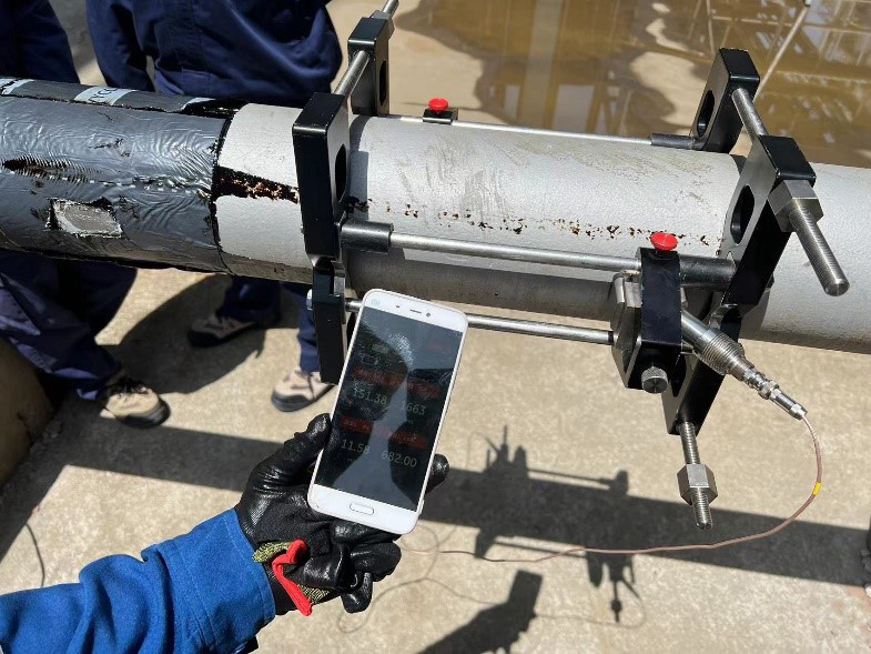
Panametrics TransPort PT900 clamp-on transducers installed on a high-pressure ethylene line

Clamp-On Ultrasonic Flow Meter Panametrics TransPort PT900

Panametrics TransPort PT900

Source: Panametrics Application Note PANA103AN (panametrics.com) — © Panametrics LLC. Localized and prepared in cooperation with INTECH CONTROL, official Panametrics representative for Slovakia and Hungary.
by Bohuslav Bobrik Bohuslav Bobrik

Panametrics Technology Improves Flow Measurement Reliability and Accuracy for the Semiconductor Industry

APPLICATION NOTE

Panametrics Technology Improves Flow Measurement Reliability and Accuracy for the Semiconductor Industry

Summary

To help optimize, track and measure its raw water usage, a South Korean chip manufacturer turned to Panametrics for solutions. The customer faced challenges with the accuracy and reliability of traditional electromagnetic flow meters from competing manufacturers, leading to difficulties reporting water usage and disparities with the national water supply company over the volumes of water used at the semiconductor site. This led to the opportunity for Panametrics to evaluate the application for a clamp-on installation.

FluidRaw water
Pipe Size and MaterialDN600 (24″) Carbon Steel
Flow Rate0 – 1,500 m³/h (0 – 6,604 GPM)
Process Temperature2 – 25 °C (35 – 77 °F)
Requested Accuracy<±1% of reading
Panametrics

Benefits:

  • Easy to set up and program
  • No process interruption
  • Strong reputation and local support
  • Reliability and accuracy
  • Various communication options available

Challenge

The customer required precision measurements but could not allow any process disruption, since the plant operates 24/7. Panametrics provided KOLAS (Korea Laboratory Accreditation Scheme) calibration and verification documents to meet the customer’s required accuracy and performance ahead of commissioning. Because wifi and bluetooth use were prohibited at the site, Panametrics’ engineers carried out a field demonstration at the measurement point using a handheld TransPort PT878 clamp-on ultrasonic flow meter. The accurate and reliable readings recorded during the demonstration matched the customer’s expectations and convinced them that Panametrics’ technology was the right choice.

Solution

For the permanent installation, the customer selected Panametrics’ AquaTrans AT600 clamp-on ultrasonic flow meter with CRS 402 transducers, communicating via RS-485 Modbus to the national water company and providing an analog output to the customer’s SCADA system. Since installation, the flow meter has delivered accurate and reliable readings, resolving the reporting discrepancies for both the customer and the national water company. Pleased with the results and seeing further opportunities to optimize operations using Panametrics’ flow technology, the customer has since ordered an additional 30 AT600 flow meters for the site in South Korea.

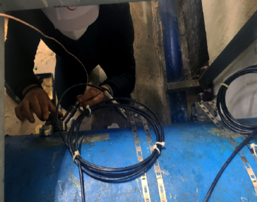
Technician installing Panametrics AquaTrans AT600 clamp-on transducers on a raw water pipeline

Ultrasonic Flow Meter for Liquids Panametrics AquaTrans AT600

Datasheet (PDF) Panametrics AquaTrans AT600

Source: Panametrics Application Note PANA092AN (panametrics.com) — © Panametrics LLC. Localized and prepared in cooperation with INTECH CONTROL, official Panametrics representative for Slovakia and Hungary.
by Bohuslav Bobrik Bohuslav Bobrik

Clamp-On Ultrasonic Flow Meters Help Semiconductor Manufacturer BOE Standardize Water Measurement

APPLICATION NOTE
Digital network visualization symbolizing semiconductor manufacturing

Clamp-On Ultrasonic Flow Meters Help Semiconductor Manufacturer BOE Standardize Water Measurement

Summary

Chip demand is at a record high today, driven further by the impact of the pandemic and the ever-increasing demand for digital technology, making the semiconductor industry one of the fastest-growing sectors. Panametrics was approached by an automation contractor on behalf of BOE, a leading manufacturer of LCD and OLED displays, to supply flow meters for a greenfield project manufacturing foldable OLED displays. Hundreds of flow meters were required across the various project milestones.

Application

Fig. 1: Water piping at a semiconductor manufacturing facility, where AquaTrans AT600 clamp-on ultrasonic flow meters are used.

FluidVarious water lines
Pipe SizeDN50 to DN1600 (2″ – 64″)
Pipe MaterialCS, SS, various plastic pipes
Process Temperature7 – 25 °C (44 – 77 °F)
Panametrics

Benefits:

  • Zero contamination risk
  • No interruption to operations
  • Low maintenance
  • No pressure drop
  • Long-term stability and drift characteristics
  • Bi-directional measurement

Challenge

The semiconductor industry has many water applications – from ultra-pure water used for cleaning, to cooling water for HVAC systems, to raw water and sewage water that is typically treated directly at the site’s own wastewater treatment plant. All of these applications require flow measurement so the customer can achieve better process control and meet reporting obligations to local authorities, so flow meters play an important role. The key requirements for both the automation contractor and the end customer, BOE, were: the ability to measure non-conductive media such as ultra-pure water; reliable and stable measurement for process control; easy installation and commissioning; maintenance-free operation; digital communication capability (HART); and versatility to fit a wide range of pipe sizes and materials.

Solution

Partnering with the Panametrics team, the customer selected AquaTrans AT600 clamp-on ultrasonic flow meters with 2 MHz, 1 MHz and 0.5 MHz transducers in a dual-traverse configuration for the best possible performance: 2 MHz transducers for pipe sizes up to DN50, 1 MHz for DN80 to DN800, and 0.5 MHz for DN850 and above. Between 2019 and 2021, BOE ordered more than 500 AT600 flow meters with HART protocol. The customer is satisfied with both the Panametrics technology and the measurement results, and Panametrics has since become an approved supplier for BOE.

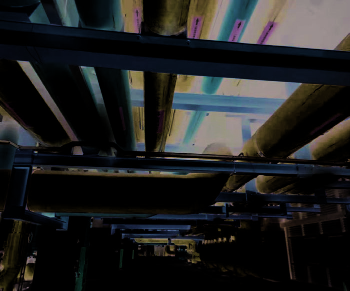
Water piping in a semiconductor fab facility

Ultrasonic liquid flow meter Panametrics AquaTrans AT600

Datasheet (PDF) Panametrics AquaTrans AT600

Source: Panametrics Application Note PANA095AN (panametrics.com) — © Panametrics LLC. Localized and prepared by INTECH CONTROL, the official Panametrics representative for Slovakia and Hungary.

by Bohuslav Bobrik Bohuslav Bobrik

Ultrasonic Gas Flow Meter Helps Steel Mill Achieve Reliable Low-Pressure Flue Gas Measurement

APPLICATION NOTE
Steel mill industrial complex at dusk with flames and smoke

Ultrasonic Gas Flow Meter Helps Steel Mill Achieve Reliable Low-Pressure Flue Gas Measurement

Summary

A major steel mill in China, with a production capacity of tens of millions of tons per year, has a long and successful track record using ultrasonic flow meters. Already very familiar with Panametrics products, the customer has used many Panametrics liquid, gas, and flare flow meters with great success. However, it was also using a competing ultrasonic flow meter for flue gas measurement. The customer found it unreliable and wanted to replace it.

Application

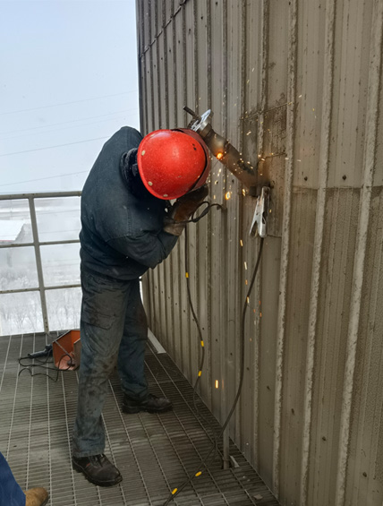
Fig. 1: Welding the downstream transducer nozzle onto the flue gas duct.

FluidFlue gas
Pipe Size and Material2410 × 4000 mm (7.9 × 13.1 ft), carbon steel
Process Temperature101 – 129 °C (214 – 264 °F)
Process Pressure-11 Pa to 93 kPa (-0.0016 to 13.5 psig)
Fluid Sound Speed~390 m/s (~1,280 ft/s)
Panametrics

Benefits:

  • Measures down to very slight vacuum pressure
  • No pressure drop
  • Low maintenance
  • Long-term stability
  • Works on rectangular pipes
  • Wide measuring range

Challenge

The flow meter had to be installed on a large 2.4 m × 4 m rectangular duct. The installation location offered only about 1.5 pipe diameters of straight run upstream, resulting in a non-fully-developed flow profile. With the two nozzles positioned far apart, achieving correct alignment was difficult — any offset risked losing signal capture and producing inaccurate, unreliable readings. There was no room for error: the measurement data feeds directly into the plant’s continuous emission monitoring system (CEMS).

Solution

Given the very long acoustic path, the Panametrics team recommended its DigitalFlow XGM868i gas ultrasonic flow transmitter with T5 transducers operating at 50 kHz. The wide beam angle of these transducers ensured an accurate measurement across the long path. In parallel, the Panametrics Services team used a laser alignment tool to achieve precise nozzle alignment. Following successful installation and commissioning, the flow meter delivered accurate and reliable data, and the customer was able to properly feed its CEMS with the required flow measurement data. Following this success, the Panametrics team is already discussing similar applications at other steel mills around the world.

Technician welding a transducer mounting nozzle onto a large flue gas duct

Panametrics DigitalFlow XGM868i process gas ultrasonic flow meter

Datasheet (PDF) Panametrics DigitalFlow XGM868i

Source: Panametrics Application Note PANA013AN (panametrics.com) — © Panametrics LLC. Localized and prepared by INTECH CONTROL, the official Panametrics representative for Slovakia and Hungary.

by Bohuslav Bobrik Bohuslav Bobrik

Ultrasonic Gas Flow Meter Helps Steel Mill Safely Control LD Converter Gas Recovery

APPLICATION NOTE
Steel mill with molten metal ladle at dusk

Ultrasonic Gas Flow Meter Helps Steel Mill Safely Control LD Converter Gas Recovery

Summary

A major steel mill in India operates one of the most advanced production lines in the country, including a high-precision Cut-to-Length line capable of processing steel coils up to 25 mm thick with edge trimming. Looking to further optimize its operations, the customer wanted to install a bidirectional gas flow meter on its Linz-Donawitz gas (LD gas) holder. The 100,000 Nm³/h LD gas holder collects gas from the SMS (Steel Melt Shop) converter and exports it through two DN1000 (40″) lines, each operating at roughly 1,000–1,200 mmWC when its booster is active. These lines feed into a DN1600 (64″) booster fan gas (BFG) network running at 900–1,100 mmWC. The customer wanted to feed LD gas into the BF gas network, but faced a safety concern: if a booster motor failed to keep the line pressure above the BFG network’s 900–1,100 mmWC during spillback, BFG gas could flow back into the LD gas holder undetected, creating a safety risk for the entire LD gas holder setup.

Application

Fig. 1: T5 Bias 90 installation with XAMP preamplifiers on the 64″ (DN1600) BFG line.

Pipe Size and Material64″ (DN1600) Sch. 40, carbon steel (API 5L)
Gas Flow Range0 – 100,000 Nm³/h
Gas TemperatureAmbient – 70 °C
Gas PressureAtmospheric – 1,600 mmWC
Gas Composition~13–15% CO₂ / ~50–70% CO / ~0.4–1.2% O₂ / ~2–3% H₂ / ~5–20 mg/Nm³ dust / moisture
Panametrics

Benefits:

  • Bidirectional flow measurement
  • Accurate, cost-effective measurement on large pipelines
  • Wide rangeability
  • Handles difficult gases (CO₂ / CO / H₂), works up to 100% CO₂
  • Local support from INTECH CONTROL

Challenge

The plant had already tried a differential pressure device and several other flow technologies, but none of them could cope with the low operating pressure, the bidirectional flow, the very wide rangeability (from almost zero flow through reverse flow up to maximum flow) and the dust content in the gas. Ultrasonic flow meters, however, can handle all of these challenges — including the signal absorption caused by high CO₂ content that defeats many other technologies.

Solution

The Panametrics sales and application engineering team reviewed the process conditions and the customer’s requirements. Drawing on extensive experience with steel mill gas applications, the team proposed the DigitalFlow XGM868i with T5 (100 kHz) transducers in a Bias 90 configuration. The flow meter was successfully installed and commissioned by the Panametrics Services team. The customer was very satisfied with the result — the measured data matched expectations — and has since deployed Panametrics ultrasonic flow meter technology on other LD gas lines throughout the same plant.

XGM868i transducers installed on a large gas pipeline

Panametrics DigitalFlow XGM868i process gas ultrasonic flow meter

Datasheet (PDF) Panametrics DigitalFlow XGM868i

Source: Panametrics Application Note PANA018AN (panametrics.com) — © Panametrics LLC. Localized and prepared by INTECH CONTROL, the official Panametrics representative for Slovakia and Hungary.
by Bohuslav Bobrik Bohuslav Bobrik

Clamp-On Ultrasonic Flowmeters Ensure Reliable Measurement of Hot Liquids with Solids

APPLICATION NOTE
Chemical production plant at dusk

Clamp-On Ultrasonic Flowmeters Ensure Reliable Measurement of Hot Liquids with Solids

Summary

Zhejiang Xinhecheng Co., Ltd., founded in 1999, manufactures functional chemicals including nutritional ingredients, fragrances and polymer materials. For a trial project, the customer needed to measure a liquid containing 10% metallic solid particles at an operating temperature of 150°C. Traditional electromagnetic and differential-pressure flowmeters proved unsuitable because electrodes and primary elements were quickly worn down by the solid particles, requiring frequent maintenance, causing unplanned shutdowns and reduced yield. Clamp-on ultrasonic technology stood out because it can be installed externally without modifying the pipe or interrupting the process.

Application

Fig. 1: C-PT 1 MHz clamp-on transducer installed on a 2″ stainless steel line carrying the hot liquid catalyst.

MediumLiquid catalyst
Pipe size and thicknessDN50 (2″)
Pipe materialSS 304
Pressure0.2 MPa (29 psig)
Flow rate5 – 30 m³/h (22 – 132 GPM)
TemperatureUp to 175°C (347°F)
Requested accuracy±1-2% of reading
Panametrics

Benefits:

  • Low to zero maintenance
  • No pressure drop
  • No process interruption
  • High reliability and long term stability

Challenge

Interrupting production was not feasible, so the operator required a solution that could be implemented without disrupting ongoing operations. As there was no prior experience with this specific application, a field test was conducted to confirm that the flowmeter could perform under the process conditions. Furthermore, the customer expected the clamp-on ultrasonic liquid flowmeter to require minimal maintenance by design.

Solution

Panametrics conducted the field test using a PT900 portable flowmeter with 1 MHz clamp-on transducers. The transducers were mounted on a vertical pipe (Fig. 1) with flow from bottom to top. As the pipe was insulated, the insulation was removed for the test, and installation took approximately 15 minutes. The customer assessed the meter accuracy by triggering the control valve and comparing the resulting changes in flow – the flowmeter responded as expected, with readings tracking the valve’s percentage opening. Satisfied with the results, the customer decided to purchase permanent clamp-on instrumentation: the XMT1000LC with C-PT 1 MHz transducers, with an initial plan for two units. The meters have now been in service for several years, continuing to meet expectations while reducing maintenance costs and improving production yield. For future installations, the customer plans to use C RS HT transducers rated up to 230°C.

C-PT 1 MHz clamp-on transducer installed on insulated 2-inch pipe

Panametrics PanaFlow LC clamp-on ultrasonic liquid flowmeter

Datasheet (PDF) Panametrics PanaFlow LC

Source: Panametrics Application Note PANA148AN (panametrics.com) — © Panametrics LLC. Localized and prepared by INTECH CONTROL, official Panametrics representative for Slovakia and Hungary.

by Bohuslav Bobrik Bohuslav Bobrik

Clamp-On Ultrasonic Flow Meters Enable Safe Measurement of High-Pressure Hydrogen Gas in Chemical Production

APPLICATION NOTE
Chemical plant producing 1,4-butanediol (BDO) with high-pressure hydrogen gas lines

Clamp-On Ultrasonic Flow Meters Enable Safe Measurement of High-Pressure Hydrogen Gas in Chemical Production

Summary

Sanwei New Materials, a Chinese chemical producer, manufactures 1,4-butanediol (BDO) – a key raw material for biodegradable plastics – using the Reppe process. In this process, hydrogen gas reacts with a copper-based catalyst to form 2-butyne-1,4-diol (BYD), which is then hydrogenated into BDO. Precisely controlling the hydrogen gas flow throughout the reaction is essential both for reaction efficiency and for keeping the finished BDO within specification. The plant operates several high-pressure hydrogen gas lines that needed a dependable flow measurement solution.

Application

Fig. 1: Panametrics clamp-on transducers installed on a high-pressure hydrogen gas line.

FluidHydrogen gas
Pipe sizeDN80 / DN100 (3″ / 4″), wall thickness 20 mm
Pipe materialCarbon steel
Process temperature60°C (140°F)
Pressure30 MPa (4,351 psig)
Density~19 kg/m³ (1.19 lb/ft³)
Flow velocity4.5 – 6.5 m/s (14.7 – 21.3 ft/s)
Panametrics

Benefits:

  • Safe – fully contactless
  • Low maintenance
  • Easy installation with no process interruption
  • No pressure drop
  • Long-term stability and drift-free performance
Panametrics clamp-on transducers installed on the hydrogen gas pipeline

Challenge

The plant traditionally measured hydrogen gas with orifice-plate meters, whose differential-pressure cells required frequent recalibration. Every recalibration meant halting the process – cutting production yield and exposing staff to serious safety risks, given hydrogen’s high operating pressure and low flammability limit. The customer needed a safer, drift-free alternative that would not interrupt operations.

Solution

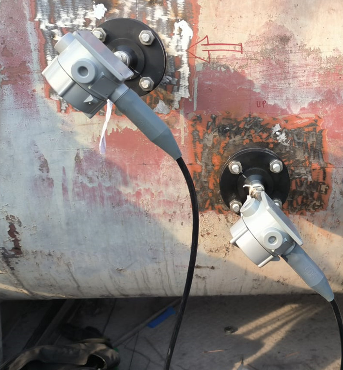
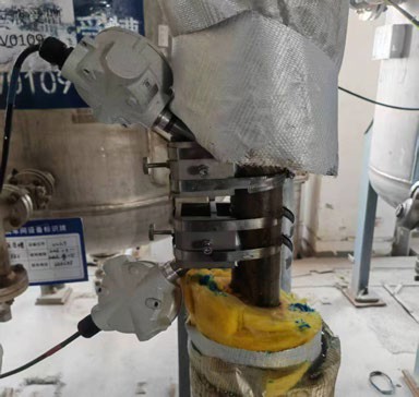
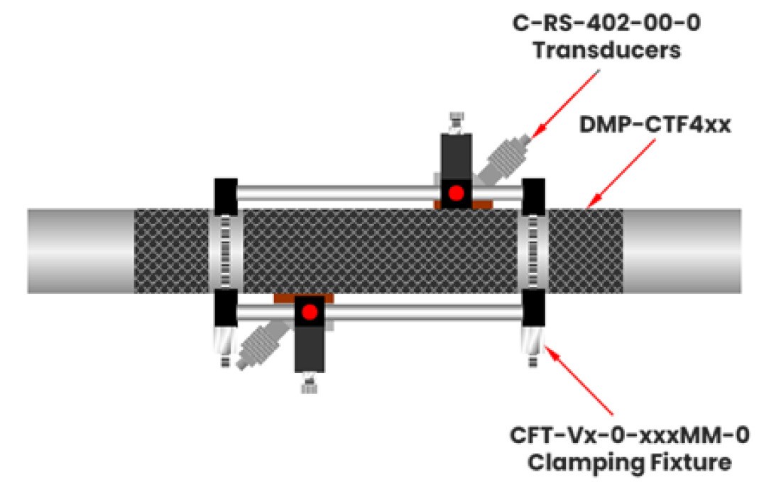
Clamp-on ultrasonic flow meters have measured hydrogen gas for almost 30 years, but clamp-on technology is rarely used at such extreme pressures: hydrogen’s low density combined with very thick, high-pressure pipe walls creates acoustic conditions that typical clamp-on gas transducers cannot handle. Panametrics tested transducers at 200 kHz, 500 kHz and 1 MHz, and found that the C-RS-402 sensor operating at 1 MHz delivered accurate, reliable results. Applying damping material around the clamping fixture and polishing the pipe surface beneath the sensors further improved signal quality. The team installed a triple-traverse configuration and configured the Panametrics XMT1000LC clamp-on flow meter (part of the PanaFlow LC platform) for high-voltage operation, raising the signal-to-noise ratio to between 5:1 and 8:1. With stable readings established, the plant’s DCS could base its process control directly on the flow-meter data. Close cooperation between the Panametrics technology and local service teams delivered a solution that now gives Sanwei New Materials more accurate, reliable hydrogen gas measurement – improving both safety and productivity.

Triple-traverse transducer installation on the hydrogen gas line
C-RS-402 transducer and clamping fixture configuration diagram
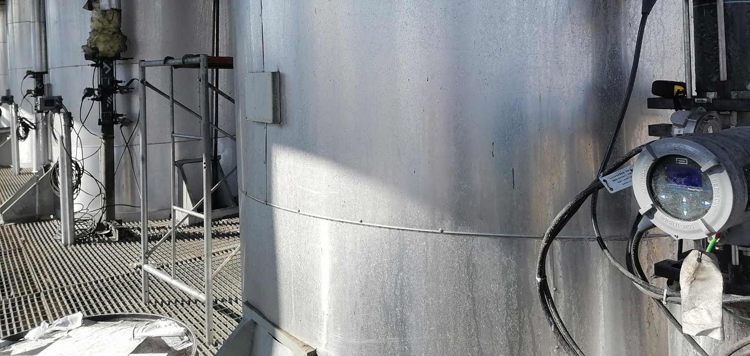
Stable flow readings displayed on the plant's DCS screen

Panametrics PanaFlow LC clamp-on ultrasonic flow meter

Datasheet (PDF) Panametrics PanaFlow LC

Source: Panametrics Application Note PANA001AN (panametrics.com) — © Panametrics LLC. Localized and prepared by INTECH CONTROL, official Panametrics representative for Slovakia and Hungary.
by Bohuslav Bobrik Bohuslav Bobrik

How Panametrics Clamp-On Flow Meter Technology Delivered Accurate Measurements of High-Velocity Water Flow in a Penstock Pipeline

APPLICATION NOTE
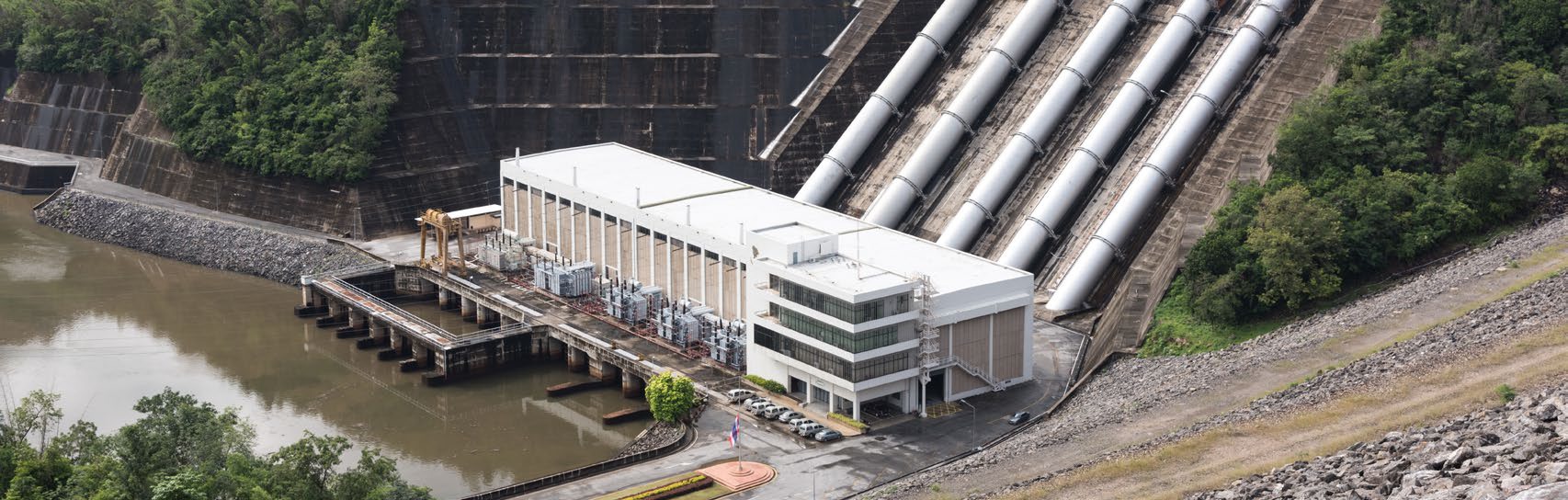
Hydropower plant with penstock pipelines

How Panametrics Clamp-On Flow Meter Technology Delivered Accurate Measurements of High-Velocity Water Flow in a Penstock Pipeline

Summary

700-meter-long penstocks at a hydroelectric power plant in China had no flow measurement to assess the water turbine efficiency and to better control the power plant performance. To address this gap, the operator evaluated three flow measurement technologies: vortex, differential pressure, and ultrasonic transit time. Before making any decision, they required a technical evaluation and a potential field test.

Application

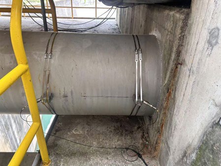
Fig. 1: C-RS 0.5MHz installed on DN700 pipe.

MediumWater
Pipe size and thicknessDN700 (32″)
Pipe materialStainless steel
Pressure0.2 MPa (29 psig)
Flow rate4-7 m³/s (63,401-110,952 GPM)
Temperature~ 25°C (77°F)
Requested accuracy± 1 to 2% of reading
Panametrics

Benefits:

  • Easy to install with no process shutdown
  • Very low maintenance
  • No pressure drop
  • Unrivalled large turndown ratio from low flow to high flow
  • Long term stability and drift characteristics
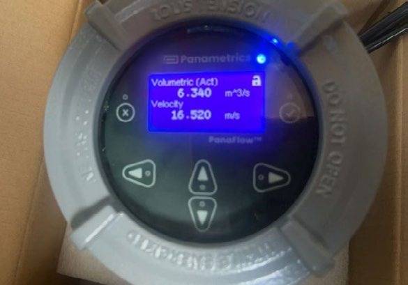
Panametrics XMT1000LC transmitter showing measured readings

Challenge

The customer’s objective was to install flowmeters on these lines with the understanding that flow velocities could exceed 15 m/s (49 ft/s). At the same time, minimizing pressure drop was critical due to the limited available head (pressure). Conventional technologies such as differential pressure devices and vortex meters were not suitable, as both introduce pressure losses and are unable to handle low-flow conditions due to inherent cut-off limitations. Ultrasonic flowmeters were ultimately pre-selected, given their ability to overcome these challenges. However, the originally trialed solution reached its upper operating limit, constrained by default factory settings that could not be overridden. As a result, an alternative solution needed to be investigated and evaluated.

Solution

The Panametrics PanaFlow LC clamp-on ultrasonic flowmeter was selected, configured as a single path XMTXP R05 in a 2-traverse set up. This configuration supports liquid flow velocities from 0.03 to 20 m/s (0.1 to 65.6 ft/s), making it well suited to the application. Installed at the same pipe location, the flowmeter immediately provided accurate measurements, confirming a flow velocity of 16.52 m/s (Fig. 2). The customer was very satisfied with PanaFlow LC’s performance, as it matched their expectations in full. It was able to better monitor the water turbine efficiency and make the needed improvements for increased efficiency. As a result, Panametrics is now established as the sole qualified flow measurement supplier on the penstock lines, with multiple PanaFlow LC flowmeters installed.

PanaFlow LC clamp-on sensor installed on DN700 pipe

Panametrics PanaFlow LC Clamp-On Ultrasonic Flowmeter

Datasheet (PDF) Panametrics PanaFlow LC

Source: Panametrics Application Note PANA153AN (panametrics.com) — © Panametrics LLC. Localized and prepared by INTECH CONTROL, the official Panametrics representative in Slovakia and Hungary.
by Bohuslav Bobrik Bohuslav Bobrik

Flow Monitoring at a Sea Water Reverse Osmosis Plant Improves Water Distribution

APPLICATION NOTE
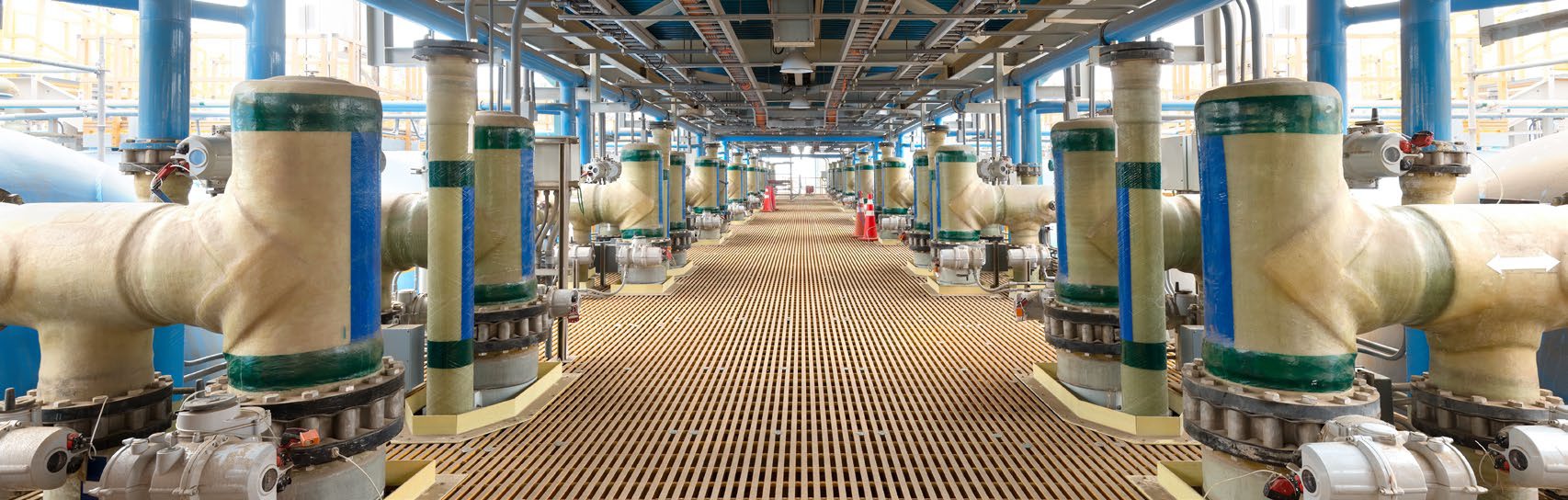
Sea Water Reverse Osmosis desalination plant

Flow Monitoring at a Sea Water Reverse Osmosis Plant Improves Water Distribution

Problem

One of the largest Sea Water Reverse Osmosis (SWRO) desalination plants in the MEATI region (Middle East, Africa, Turkey and India) asked a Panametrics Channel Partner to verify its existing magnetic flowmeters. Because magnetic flow measurement requires periodic calibration, the plant’s maintenance team wanted a practical verification method suited to both permanent and portable installations on large-diameter pipes. The pipework itself added to the challenge, combining HDPE (high-density polyethylene) and GRP (glass-reinforced plastic) pipe ranging from 800 mm to 1600 mm (32″ to 64″) in diameter. Measurements were needed at the pipeline’s outlet from the SWRO plant, feeding the distribution network, so that flow readings taken next to the existing magnetic flowmeters could be used for an accurate water balance calculation.

Application

Pipe SizeDN1200 (48″)
MaterialGRP (Glass Reinforced Plastic)
Wall Thickness7 mm
Straight Runs20D upstream / 15D downstream
Panametrics

Benefits:

  • Easy to set up
  • No mechanical modification
  • Superior technology
  • No process interruption
  • No downtime and acceptable accuracy / repeatability
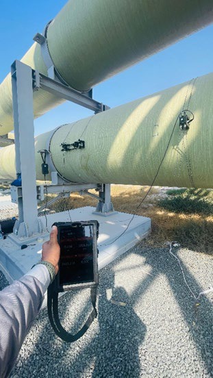
PT900 clamp-on flow meter with transducers on a DN1200 GRP pipe

Challenge

The customer needed an accurate, repeatable flow measurement solution that was easy to install and would not interrupt plant operations — mechanically modifying the existing inline magnetic flowmeters on the water network was not an option. After trialling several clamp-on ultrasonic flow meters, the Channel Partner demonstrated Panametrics’ technology with a dual-traverse installation on the 1200 mm GRP pipeline, mounting two transducers on the same side of the pipe. Compared with the competing options tested, the customer found the Panametrics setup delivered faster, more accurate and more reliable results.

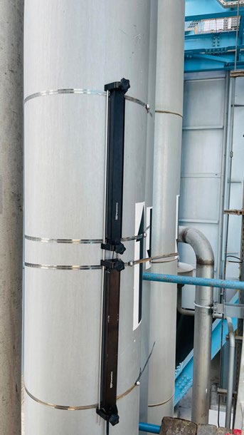
AquaTrans AT600 transducers mounted on a DN600 HDPE pipe

Solution

The successful demonstration used TransPort PT900 and AquaTrans AT600 ultrasonic clamp-on flow meters, achieving a 1–2% match against the existing magnetic flowmeters and confirming their performance. Following the demo, the customer placed an order and now runs a permanent flow meter solution — combining 1 MHz and 0.5 MHz transducers — on the SWRO plant’s main outlet line, together with a portable unit for periodic checks on the permanent magnetic flowmeters. Despite the large pipe sizes and demanding pipe materials, the customer now benefits from a dual-traverse installation whose accuracy and reliability support process monitoring, an accurate plant balance, and improved overall efficiency and productivity.

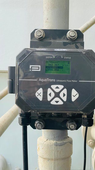
AquaTrans AT600 local display showing a flow reading

Ultrasonic liquid flow meter Panametrics AquaTrans AT600

Datasheet (PDF) AquaTrans AT600

Source: Panametrics Application Note (panametrics.com) — © Panametrics LLC. Localized and adapted by INTECH CONTROL, official Panametrics representative in the Slovak Republic and Hungary.

by Bohuslav Bobrik Bohuslav Bobrik

Brine Flow Measurement in a Geothermal Power Plant

APPLICATION NOTE
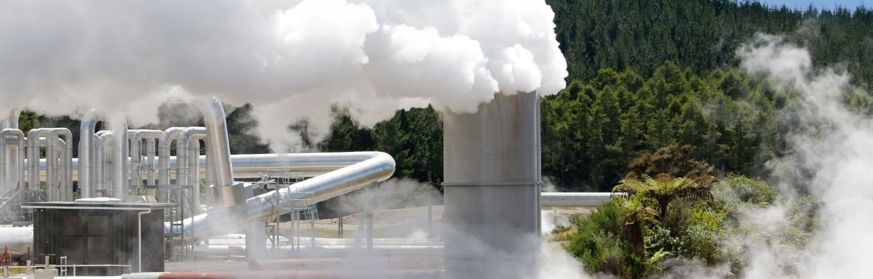
Geothermal power plant

Brine Flow Measurement in a Geothermal Power Plant

Problem

Geothermal power plants harness hydrothermal resources containing both hot water (brine) and steam, with the steam driving turbines connected to electricity generators. Brine temperatures typically range from 140°C to 200°C depending on the well. A separator divides the two streams: steam flows on to the turbines, while the brine feeds the plant’s heat exchangers. Accurately measuring geothermal brine flow is essential to well efficiency — it lets operators optimize flow rates and calculate the right dose of scale and corrosion inhibitor needed to sustain or improve well productivity, which in turn can boost well yield and overall power generation capacity. Seeing an opportunity to improve its brine flow measurement process, a South-Eastern European geothermal energy company turned to Panametrics.

Application

MediumGeothermal brine
Temperature170°C (338°F)
Pressure10 barg (145 psig)
Pipe12″ Sch 40 CS
Flow rate400 m³/h maximum (1.5 m/s) / 1,761 GPM (4.9 ft/s)
Panametrics

Benefits:

  • Easy to set up
  • Easy to operate
  • No process shutdown
  • No downtime and no periodic maintenance or calibration needed
  • Reliable
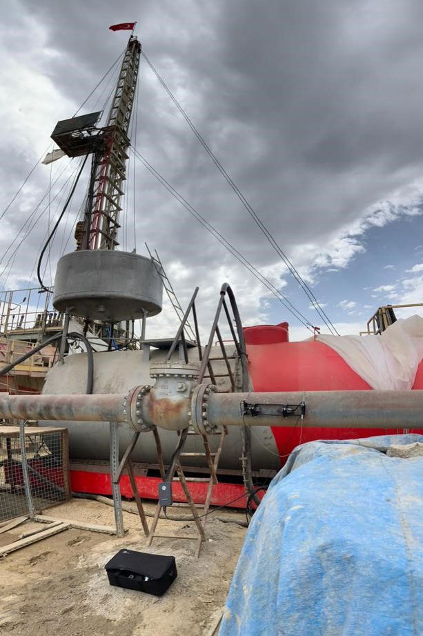
Flow measurement equipment at a geothermal wellhead

Challenge

The plant had previously relied on other flow measurement technologies to monitor brine, but differential-pressure and electromagnetic flow meters struggled under the harsh operating conditions: solid content caused erosion, and high temperatures took a toll on accuracy. Beyond the technical shortcomings, the customer was frustrated that repairing, refurbishing, or calibrating these meters required shutting the process down entirely, resulting in costly production losses during turnarounds.

Solution

To verify actual flow conditions, Panametrics carried out flow tests using the TransPort PT900 Portable Ultrasonic Flowmeter. Its built-in data logger let the team record and store readings from each well tested, while the battery-powered design meant flow rates could be confirmed at remote wellheads without any external power supply. Because the PT900 clamps onto the outside of the pipe, it could be installed quickly without interrupting the process — a feature the customer valued highly. Following a successful measurement campaign, the customer went on to install nine permanent AquaTrans AT600 flow meters fitted with high-temperature transducers. The plant now benefits from highly accurate, reliable flow measurement with zero downtime for calibration or unplanned repairs.

Ultrasonic liquid flow meter Panametrics AquaTrans AT600

Datasheet (PDF) AquaTrans AT600

Source: Panametrics Application Note (panametrics.com) — © Panametrics LLC. Localized and adapted by INTECH CONTROL, official Panametrics representative in the Slovak Republic and Hungary.