by Bohuslav Bobrik Bohuslav Bobrik

Clamp-On Ultrasonic Flow Meters Enable Safe Measurement of High-Pressure Hydrogen Gas in Chemical Production

APPLICATION NOTE
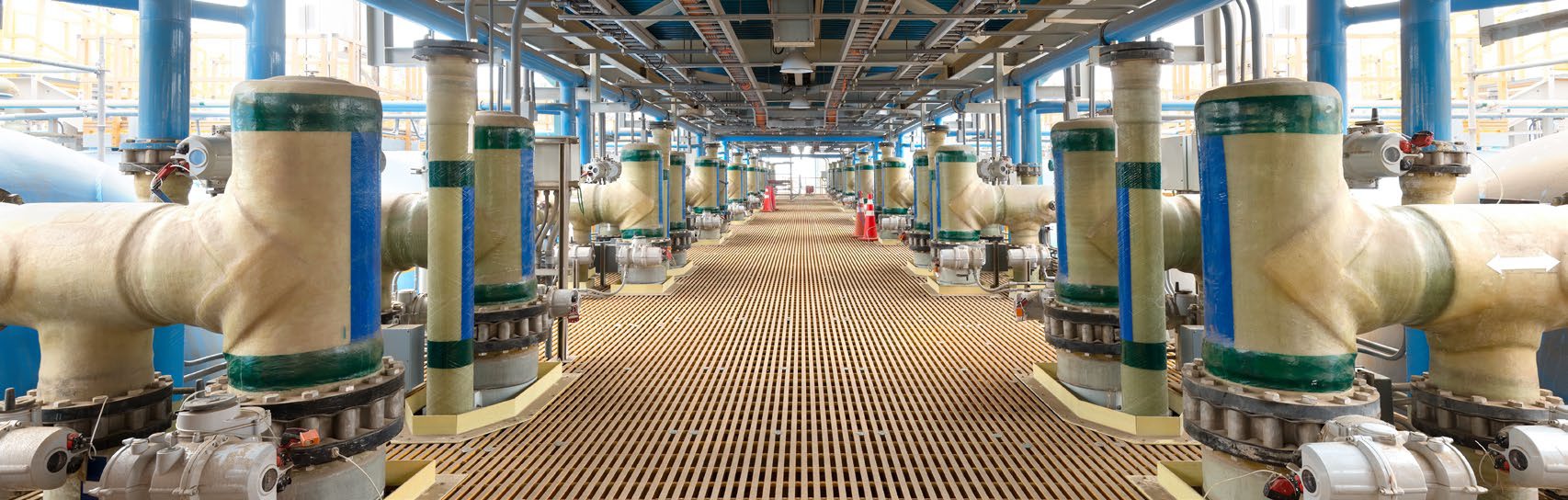
Chemical plant producing 1,4-butanediol (BDO) with high-pressure hydrogen gas lines

Clamp-On Ultrasonic Flow Meters Enable Safe Measurement of High-Pressure Hydrogen Gas in Chemical Production

Summary

Sanwei New Materials, a Chinese chemical producer, manufactures 1,4-butanediol (BDO) – a key raw material for biodegradable plastics – using the Reppe process. In this process, hydrogen gas reacts with a copper-based catalyst to form 2-butyne-1,4-diol (BYD), which is then hydrogenated into BDO. Precisely controlling the hydrogen gas flow throughout the reaction is essential both for reaction efficiency and for keeping the finished BDO within specification. The plant operates several high-pressure hydrogen gas lines that needed a dependable flow measurement solution.

Application

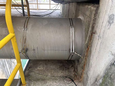
Fig. 1: Panametrics clamp-on transducers installed on a high-pressure hydrogen gas line.

FluidHydrogen gas
Pipe sizeDN80 / DN100 (3″ / 4″), wall thickness 20 mm
Pipe materialCarbon steel
Process temperature60°C (140°F)
Pressure30 MPa (4,351 psig)
Density~19 kg/m³ (1.19 lb/ft³)
Flow velocity4.5 – 6.5 m/s (14.7 – 21.3 ft/s)
Panametrics

Benefits:

  • Safe – fully contactless
  • Low maintenance
  • Easy installation with no process interruption
  • No pressure drop
  • Long-term stability and drift-free performance
Panametrics clamp-on transducers installed on the hydrogen gas pipeline

Challenge

The plant traditionally measured hydrogen gas with orifice-plate meters, whose differential-pressure cells required frequent recalibration. Every recalibration meant halting the process – cutting production yield and exposing staff to serious safety risks, given hydrogen’s high operating pressure and low flammability limit. The customer needed a safer, drift-free alternative that would not interrupt operations.

Solution

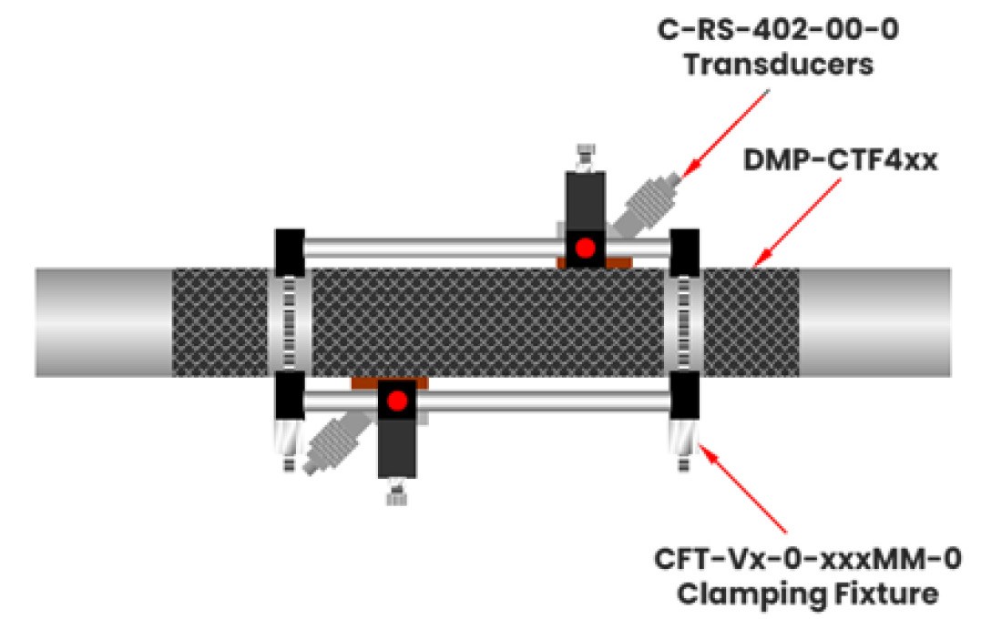
Clamp-on ultrasonic flow meters have measured hydrogen gas for almost 30 years, but clamp-on technology is rarely used at such extreme pressures: hydrogen’s low density combined with very thick, high-pressure pipe walls creates acoustic conditions that typical clamp-on gas transducers cannot handle. Panametrics tested transducers at 200 kHz, 500 kHz and 1 MHz, and found that the C-RS-402 sensor operating at 1 MHz delivered accurate, reliable results. Applying damping material around the clamping fixture and polishing the pipe surface beneath the sensors further improved signal quality. The team installed a triple-traverse configuration and configured the Panametrics XMT1000LC clamp-on flow meter (part of the PanaFlow LC platform) for high-voltage operation, raising the signal-to-noise ratio to between 5:1 and 8:1. With stable readings established, the plant’s DCS could base its process control directly on the flow-meter data. Close cooperation between the Panametrics technology and local service teams delivered a solution that now gives Sanwei New Materials more accurate, reliable hydrogen gas measurement – improving both safety and productivity.
Triple-traverse transducer installation on the hydrogen gas line
C-RS-402 transducer and clamping fixture configuration diagram
Stable flow readings displayed on the plant's DCS screen

Panametrics PanaFlow LC clamp-on ultrasonic flow meter

Datasheet (PDF) Panametrics PanaFlow LC

Source: Panametrics Application Note PANA001AN (panametrics.com) — © Panametrics LLC. Localized and prepared by INTECH CONTROL, official Panametrics representative for Slovakia and Hungary.
by Bohuslav Bobrik Bohuslav Bobrik

How Panametrics Clamp-On Flow Meter Technology Delivered Accurate Measurements of High-Velocity Water Flow in a Penstock Pipeline

APPLICATION NOTE
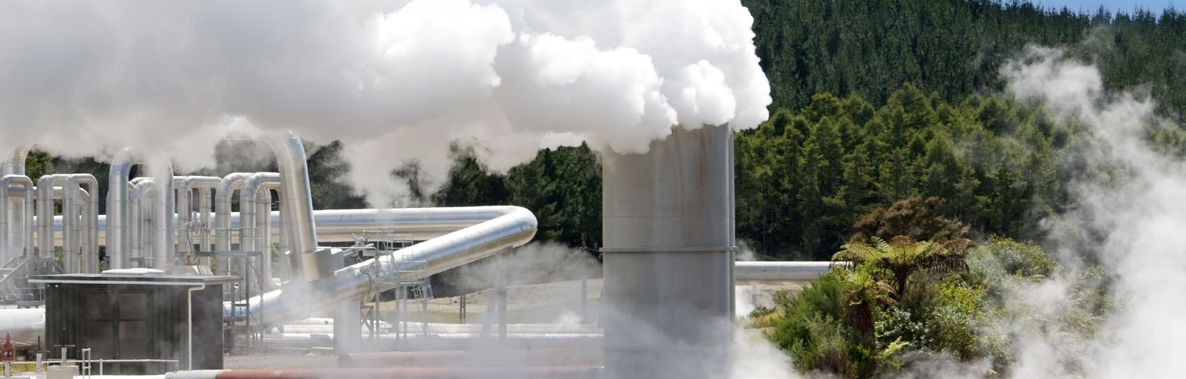
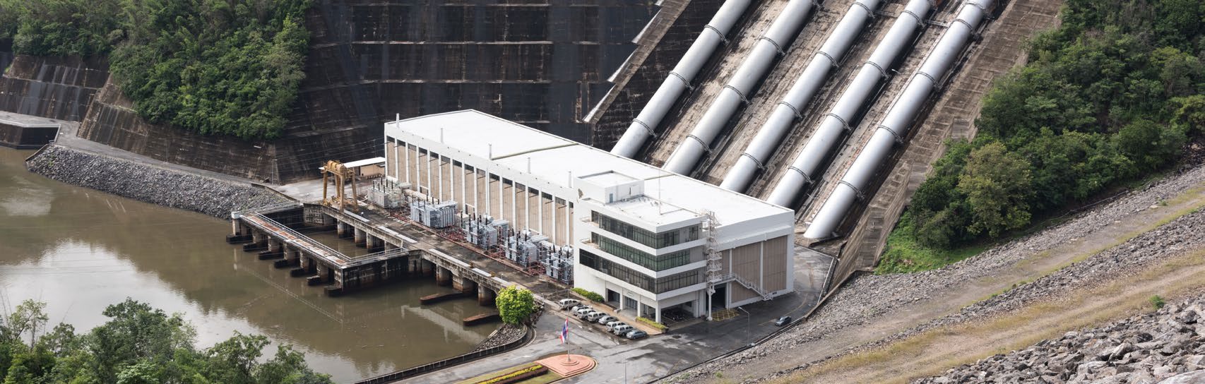
Hydropower plant with penstock pipelines

How Panametrics Clamp-On Flow Meter Technology Delivered Accurate Measurements of High-Velocity Water Flow in a Penstock Pipeline

Summary

700-meter-long penstocks at a hydroelectric power plant in China had no flow measurement to assess the water turbine efficiency and to better control the power plant performance. To address this gap, the operator evaluated three flow measurement technologies: vortex, differential pressure, and ultrasonic transit time. Before making any decision, they required a technical evaluation and a potential field test.

Application

Fig. 1: C-RS 0.5MHz installed on DN700 pipe.

MediumWater
Pipe size and thicknessDN700 (32″)
Pipe materialStainless steel
Pressure0.2 MPa (29 psig)
Flow rate4-7 m³/s (63,401-110,952 GPM)
Temperature~ 25°C (77°F)
Requested accuracy± 1 to 2% of reading
Panametrics

Benefits:

  • Easy to install with no process shutdown
  • Very low maintenance
  • No pressure drop
  • Unrivalled large turndown ratio from low flow to high flow
  • Long term stability and drift characteristics
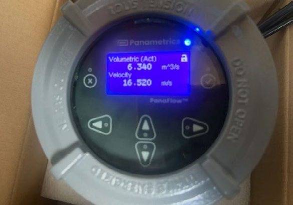
Panametrics XMT1000LC transmitter showing measured readings

Challenge

The customer’s objective was to install flowmeters on these lines with the understanding that flow velocities could exceed 15 m/s (49 ft/s). At the same time, minimizing pressure drop was critical due to the limited available head (pressure). Conventional technologies such as differential pressure devices and vortex meters were not suitable, as both introduce pressure losses and are unable to handle low-flow conditions due to inherent cut-off limitations. Ultrasonic flowmeters were ultimately pre-selected, given their ability to overcome these challenges. However, the originally trialed solution reached its upper operating limit, constrained by default factory settings that could not be overridden. As a result, an alternative solution needed to be investigated and evaluated.

Solution

The Panametrics PanaFlow LC clamp-on ultrasonic flowmeter was selected, configured as a single path XMTXP R05 in a 2-traverse set up. This configuration supports liquid flow velocities from 0.03 to 20 m/s (0.1 to 65.6 ft/s), making it well suited to the application. Installed at the same pipe location, the flowmeter immediately provided accurate measurements, confirming a flow velocity of 16.52 m/s (Fig. 2). The customer was very satisfied with PanaFlow LC’s performance, as it matched their expectations in full. It was able to better monitor the water turbine efficiency and make the needed improvements for increased efficiency. As a result, Panametrics is now established as the sole qualified flow measurement supplier on the penstock lines, with multiple PanaFlow LC flowmeters installed.

PanaFlow LC clamp-on sensor installed on DN700 pipe

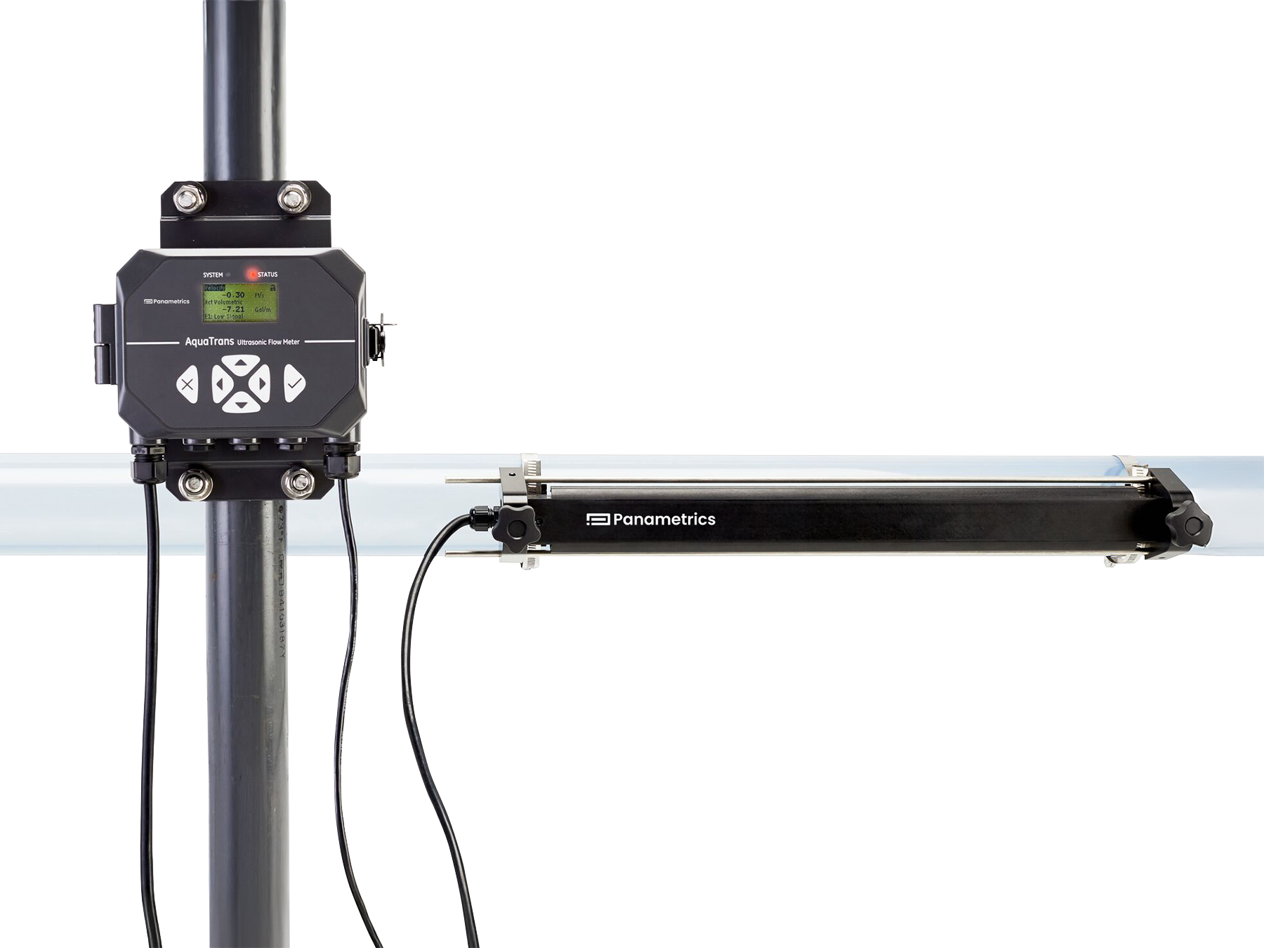
Panametrics PanaFlow LC Clamp-On Ultrasonic Flowmeter

Datasheet (PDF) Panametrics PanaFlow LC

Source: Panametrics Application Note PANA153AN (panametrics.com) — © Panametrics LLC. Localized and prepared by INTECH CONTROL, the official Panametrics representative in Slovakia and Hungary.
by Bohuslav Bobrik Bohuslav Bobrik

Portable Moisture Measurement Ensures Safe and Efficient Operation of LNG Plants

APPLICATION NOTE
LNG carrier ship loading liquefied natural gas

Portable Moisture Measurement Ensures Safe and Efficient Operation of LNG Plants

Summary

The LNG value chain — extraction and pre-treatment, transport to a processing facility, liquefaction, and distribution to end users — depends on tight moisture control at every stage. Excess moisture corrodes pipelines, damages compressors and cryogenic heat exchangers, and threatens product quality. A portable aluminum oxide moisture analyzer gives plant staff a practical way to check moisture levels throughout the process, especially during start-ups and maintenance.

Application

Portable analyzers are used to check online instruments and take spot measurements during normal operation and start-ups. Key measurement points across the LNG value chain include:

Extraction & DryingTEG (triethylene glycol) contactors at onshore and offshore platforms
ProcessingFuel gas dryers and LNG molecular sieve dryer bed outlets
PurgingNitrogen purging of the metal infrastructure to remove ambient moisture
TransportationMetering skids monitoring moisture levels during transport
UtilitiesInstrument air, nitrogen and other utility gases
Panametrics

Benefits:

  • Improved start-up efficiency
  • Enhanced equipment protection
  • Accurate and reliable measurement
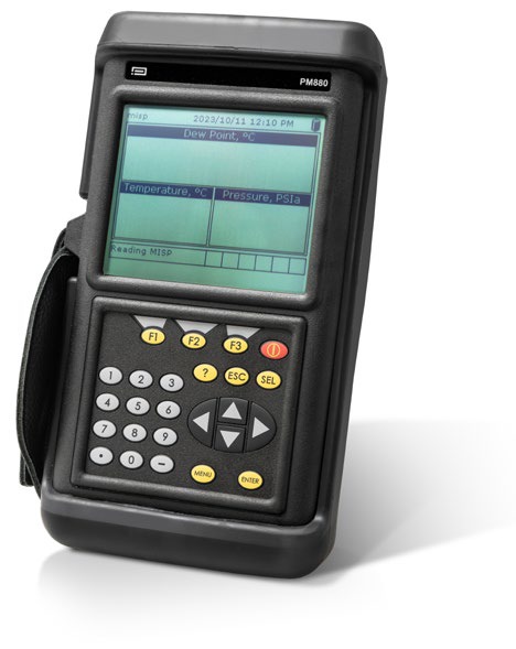
Panametrics PM880 portable moisture analyzer

Challenge

LNG plants must keep moisture under tight control even though conditions are demanding. Moisture levels vary during start-up sequences and after maintenance, and excess moisture accelerates corrosion and damages equipment, driving up maintenance and repair costs. Measuring accurately is itself a challenge in the extreme temperatures and pressures typical of LNG service. Left unchecked, moisture can freeze in the cryogenic section of the plant, causing hydrate formation, flow blockages and higher energy consumption. Because of this, start-up nitrogen purging of the LNG train’s metal infrastructure has to run long enough to remove residual moisture and keep wet gas out of the cryogenic section — but running it longer than necessary costs valuable production time.

Solution

Panametrics PM880 portable aluminum oxide analyzers measure moisture content at various points across the LNG value chain, particularly during start-ups and maintenance, directly at line pressure — so operators see actual process conditions rather than lab estimates. During nitrogen purging, the PM880 is used to confirm in real time when moisture has dropped below approximately 10 ppm, the threshold at which the purge can be considered complete and the LNG process safely started. The analyzer is built to withstand the extreme temperatures and pressures typical of LNG plants and reports moisture as water dew point or in parts per million (ppmv).

LNG value chain from natural gas pipeline to LNG tanker

Panametrics PM880 Portable Moisture Analyzer

Datasheet (PDF) Panametrics PM880

Source: Panametrics Application Note PANA004AN (panametrics.com) — © Panametrics LLC. Localized and prepared by INTECH CONTROL, the official Panametrics representative in Slovakia and Hungary.
by Bohuslav Bobrik Bohuslav Bobrik

Hydrogen Purity Measurement Ensures Safe and Efficient Operation of Hydrogen-Cooled Generators

APPLICATION NOTE
Hydrogen-cooled electricity generator

Hydrogen Purity Measurement Ensures Safe and Efficient Operation of Hydrogen-Cooled Generators

Problem

Hydrogen is used as the cooling medium in large electricity generators due to its high thermal conductivity and low viscosity, which prevents efficiency losses from increased drag or windage on the rotor. The high rotational speed of large diameter rotors generates heat, so the rotor side of the generator set requires high rates of cooling at low drag for efficiency. The hydrogen is pumped from the generator into a closed drier and cooling system before re-entering the generator. Contamination with air must be avoided to mitigate the risk of explosion, prevent early failure of mechanical components, and reduce inefficiency. A reduction in hydrogen purity from 97% to 95%, for example, can increase windage losses by as much as 32%. Removing oxygen also reduces the potential for damage to the winding insulation caused by corona discharges.

Application

Regular operation80% – 100% H₂ in air
Purging0% – 100% air in CO₂
Scavenging0% – 100% CO₂ in H₂
Panametrics

Benefits:

  • Highly robust analyzer capable of measuring all required ranges, with high reliability driven by having no moving parts and proven industry references
  • Turnkey solution with full sample handling capabilities
  • Simple field calibration
Panametrics XMTCpro thermal conductivity analyzer

Challenge

The challenge for the customer is to ensure that their closed-loop hydrogen system has an accurate and reliable measurement of hydrogen purity so that the safety and efficiency of the generator set is maintained. While customers typically measure hydrogen leaks to atmosphere outside the generator with ambient monitors, the primary measurement is on the purity within the closed-loop system. During regular maintenance intervals, there is also a requirement to enter the generator housing and vent it to atmosphere. To avoid the risk of explosion from mixing hydrogen with air, a scavenging system is used to first displace the hydrogen with an inert gas such as CO₂. Only when measurement confirms that the hydrogen has been displaced is the CO₂ in turn displaced with air, and only once measurement confirms that air is present can maintenance be safely carried out.

Solution

The Panametrics XMTCpro thermal conductivity analyzer is perfect for this application. This solution has the added advantage of being able to measure the two other gas ranges during start-up purging and shut-down scavenging. During start-up, the XMTCpro is set to measure air in CO₂. When the analyzer confirms a full CO₂ atmosphere, hydrogen is introduced and the XMTCpro is set to measure H₂ in CO₂. Once full displacement has been achieved, the analyzer is set to measure air in hydrogen. For shut-down, the process is reversed, and the XMTCpro analyzer again measures and confirms the scavenging of the relevant gases.

Panametrics XMTCpro Thermal Conductivity Analyzer

Datasheet (PDF) Panametrics XMTCpro

Source: Panametrics Application Note PANA051AN (panametrics.com) — © Panametrics LLC. Localized and prepared by INTECH CONTROL, the official Panametrics representative in Slovakia and Hungary.
by Bohuslav Bobrik Bohuslav Bobrik

Oxygen Measurement in Reactor Feed Gas Ensures Reliable Formaldehyde Production

APPLICATION NOTE
Panametrics XMO2pro – oxygen measurement in reactor feed gas

Oxygen Measurement in Reactor Feed Gas Ensures Reliable Formaldehyde Production

Problem

Oxygen is commonly measured in reactor feed gases or reactor head spaces. One such application is the industrial production of formaldehyde. Formaldehyde is produced by mixing specific amounts of methanol vapor with oxygen in a reactor in the presence of a catalyst, most commonly metal oxides. This method keeps the methanol vapor below the explosive limit that would be surpassed by more traditional techniques using a silver catalyst. With 80% of the production cost of formaldehyde being made up of the raw material used in the reaction, the oxygen content within the reactor must be controlled at an optimum level to produce a successful yield.

Application

Application0% to 21% O₂ in N₂ saturated with methanol vapors
TemperatureAmbient
Pressure5 psig (≈0.34 bar)
Panametrics

Benefits:

  • No moving parts to be fouled by liquid carryover
  • Sensor is not consumed as with galvanic fuel cells
  • Simple field calibration
  • Turnkey sample conditioning system
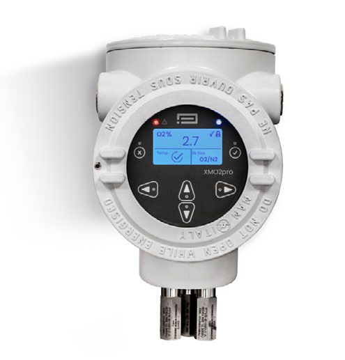
Panametrics XMO2pro oxygen analyzer

Challenge

The challenge in this application relates to the potential for liquid carryover to the oxygen analyzer, along with the reliability of the measurement. Traditional dumbbell-type paramagnetic sensors have been used in the past for these applications; however, they required extensive maintenance. Liquid carryover is extremely damaging to these units, so the challenge is to use an oxygen analyzer with minimal maintenance requirements and the durability to recover from process upsets.

Solution

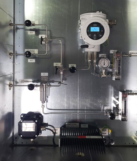
Air is used as the source of oxygen in the formaldehyde production process. The air and methanol vapor mixture is sampled at the inlet to the reactor. The XMO2pro thermoparamagnetic oxygen transmitter verifies that the optimal amount of oxygen — typically 9.8% — is present to achieve a complete reaction with minimal waste. The sample system is mounted near the sample point to prevent measurement lag time. A typical installation includes the thermoparamagnetic oxygen transmitter, a display/controller and a sample system. The sample system components — including the inlet and calibration valves, a filter/coalescer assembly, pressure gauge and flowmeter — are normally plate-mounted.

Sample system diagram with XMO2pro oxygen analyzer

Panametrics XMO2pro Oxygen Analyzer

Datasheet (PDF) Panametrics XMO2pro

Source: Panametrics Application Note PANA059AN (panametrics.com) — © Panametrics LLC. Localized and prepared by INTECH CONTROL, the official Panametrics representative in Slovakia and Hungary.
by Bohuslav Bobrik Bohuslav Bobrik

Flow Monitoring at a Sea Water Reverse Osmosis Plant Improves Water Distribution

APPLICATION NOTE
Sea Water Reverse Osmosis desalination plant

Flow Monitoring at a Sea Water Reverse Osmosis Plant Improves Water Distribution

Problem

One of the largest Sea Water Reverse Osmosis (SWRO) desalination plants in the MEATI region (Middle East, Africa, Turkey and India) asked a Panametrics Channel Partner to verify its existing magnetic flowmeters. Because magnetic flow measurement requires periodic calibration, the plant’s maintenance team wanted a practical verification method suited to both permanent and portable installations on large-diameter pipes. The pipework itself added to the challenge, combining HDPE (high-density polyethylene) and GRP (glass-reinforced plastic) pipe ranging from 800 mm to 1600 mm (32″ to 64″) in diameter. Measurements were needed at the pipeline’s outlet from the SWRO plant, feeding the distribution network, so that flow readings taken next to the existing magnetic flowmeters could be used for an accurate water balance calculation.

Application

Pipe SizeDN1200 (48″)
MaterialGRP (Glass Reinforced Plastic)
Wall Thickness7 mm
Straight Runs20D upstream / 15D downstream
Panametrics

Benefits:

  • Easy to set up
  • No mechanical modification
  • Superior technology
  • No process interruption
  • No downtime and acceptable accuracy / repeatability
PT900 clamp-on flow meter with transducers on a DN1200 GRP pipe

Challenge

The customer needed an accurate, repeatable flow measurement solution that was easy to install and would not interrupt plant operations — mechanically modifying the existing inline magnetic flowmeters on the water network was not an option. After trialling several clamp-on ultrasonic flow meters, the Channel Partner demonstrated Panametrics’ technology with a dual-traverse installation on the 1200 mm GRP pipeline, mounting two transducers on the same side of the pipe. Compared with the competing options tested, the customer found the Panametrics setup delivered faster, more accurate and more reliable results.

AquaTrans AT600 transducers mounted on a DN600 HDPE pipe

Solution

The successful demonstration used TransPort PT900 and AquaTrans AT600 ultrasonic clamp-on flow meters, achieving a 1–2% match against the existing magnetic flowmeters and confirming their performance. Following the demo, the customer placed an order and now runs a permanent flow meter solution — combining 1 MHz and 0.5 MHz transducers — on the SWRO plant’s main outlet line, together with a portable unit for periodic checks on the permanent magnetic flowmeters. Despite the large pipe sizes and demanding pipe materials, the customer now benefits from a dual-traverse installation whose accuracy and reliability support process monitoring, an accurate plant balance, and improved overall efficiency and productivity.

AquaTrans AT600 local display showing a flow reading

Ultrasonic liquid flow meter Panametrics AquaTrans AT600

Datasheet (PDF) AquaTrans AT600

Source: Panametrics Application Note (panametrics.com) — © Panametrics LLC. Localized and adapted by INTECH CONTROL, official Panametrics representative in the Slovak Republic and Hungary.

by Bohuslav Bobrik Bohuslav Bobrik

Brine Flow Measurement in a Geothermal Power Plant

APPLICATION NOTE
Geothermal power plant

Brine Flow Measurement in a Geothermal Power Plant

Problem

Geothermal power plants harness hydrothermal resources containing both hot water (brine) and steam, with the steam driving turbines connected to electricity generators. Brine temperatures typically range from 140°C to 200°C depending on the well. A separator divides the two streams: steam flows on to the turbines, while the brine feeds the plant’s heat exchangers. Accurately measuring geothermal brine flow is essential to well efficiency — it lets operators optimize flow rates and calculate the right dose of scale and corrosion inhibitor needed to sustain or improve well productivity, which in turn can boost well yield and overall power generation capacity. Seeing an opportunity to improve its brine flow measurement process, a South-Eastern European geothermal energy company turned to Panametrics.

Application

MediumGeothermal brine
Temperature170°C (338°F)
Pressure10 barg (145 psig)
Pipe12″ Sch 40 CS
Flow rate400 m³/h maximum (1.5 m/s) / 1,761 GPM (4.9 ft/s)
Panametrics

Benefits:

  • Easy to set up
  • Easy to operate
  • No process shutdown
  • No downtime and no periodic maintenance or calibration needed
  • Reliable
Flow measurement equipment at a geothermal wellhead

Challenge

The plant had previously relied on other flow measurement technologies to monitor brine, but differential-pressure and electromagnetic flow meters struggled under the harsh operating conditions: solid content caused erosion, and high temperatures took a toll on accuracy. Beyond the technical shortcomings, the customer was frustrated that repairing, refurbishing, or calibrating these meters required shutting the process down entirely, resulting in costly production losses during turnarounds.

Solution

To verify actual flow conditions, Panametrics carried out flow tests using the TransPort PT900 Portable Ultrasonic Flowmeter. Its built-in data logger let the team record and store readings from each well tested, while the battery-powered design meant flow rates could be confirmed at remote wellheads without any external power supply. Because the PT900 clamps onto the outside of the pipe, it could be installed quickly without interrupting the process — a feature the customer valued highly. Following a successful measurement campaign, the customer went on to install nine permanent AquaTrans AT600 flow meters fitted with high-temperature transducers. The plant now benefits from highly accurate, reliable flow measurement with zero downtime for calibration or unplanned repairs.

Ultrasonic liquid flow meter Panametrics AquaTrans AT600

Datasheet (PDF) AquaTrans AT600

Source: Panametrics Application Note (panametrics.com) — © Panametrics LLC. Localized and adapted by INTECH CONTROL, official Panametrics representative in the Slovak Republic and Hungary.

by Bohuslav Bobrik Bohuslav Bobrik

Airport Turns to Panametrics for Reliable Sewage Flow Measurement

APPLICATION NOTE
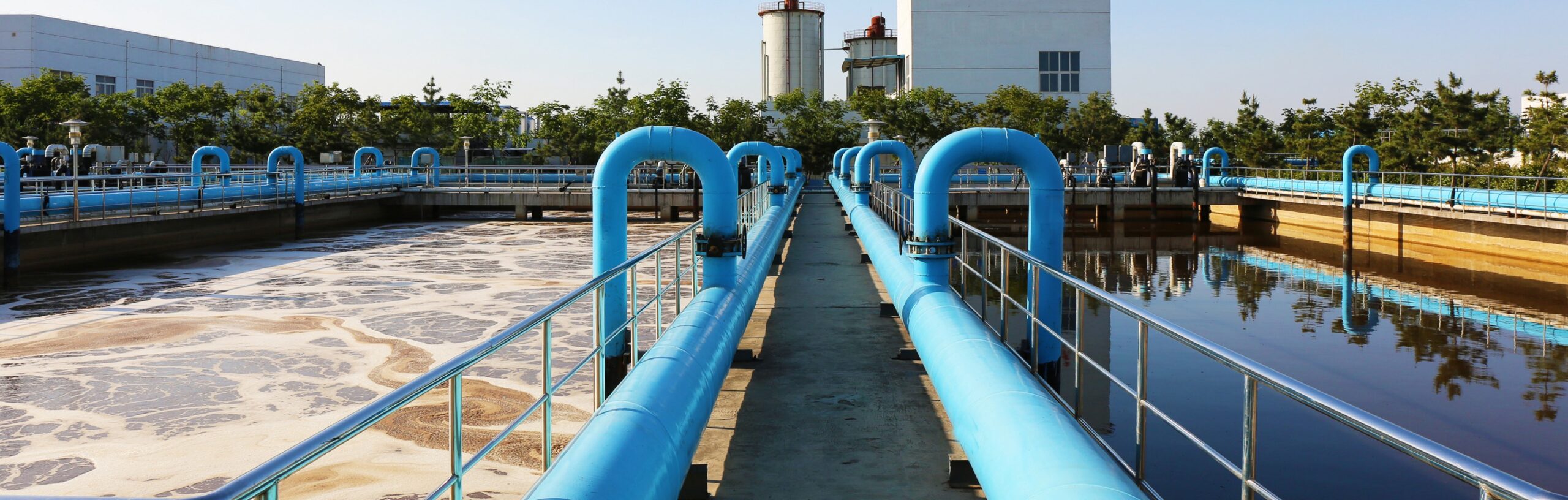
Wastewater treatment plant

Airport Turns to Panametrics for Reliable Sewage Flow Measurement

Problem

An international airport in the Middle East monitored sewage water flowing to its treatment station using an electromagnetic flow meter, but reported inconsistent readings. When a service technician inspected the meter, they found the liner had been damaged and needed to be replaced with a unit using a different lining material. Replacing it would have meant shutting down the line, draining the fluid, renting a crane, and swapping the meter — with the total cost, including at least a full day of lost line availability, far exceeding the price of the meter itself.

Application

MediumSewage water with up to 5% solids by volume
Pipe720 mm (~28″), wall thickness 10 mm
TemperatureAmbient
Accuracy requirement±1–2% of reading
Panametrics

Benefits:

  • Reliable, accurate flow measurement
  • No process interruption
  • Installs on the outside of the pipe
  • Extremely cost-effective solution
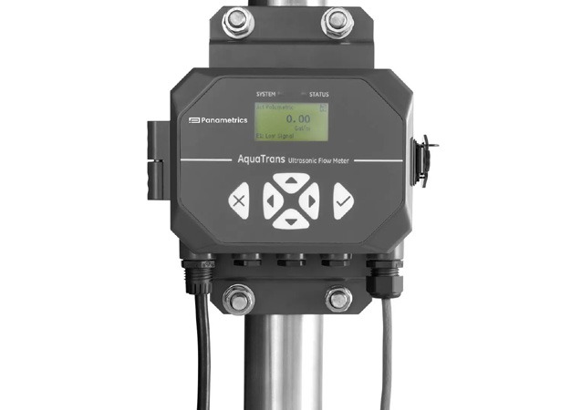
AquaTrans AT600 clamp-on ultrasonic flow meter

Solution

The airport already had a Panametrics AquaTrans AT600 clamp-on ultrasonic flow meter running to their satisfaction in the chiller plant. Although initially hesitant to use a clamp-on meter on sewage water carrying 5% solids by volume, they installed an AT600 as a trial — since it could be mounted immediately without interrupting the line. After the trial, the airport was fully satisfied with the meter’s stability and accuracy, and plans to install additional AquaTrans units at the site.

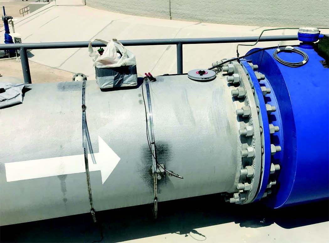
AquaTrans AT600 clamp-on flow meter installed on a 720 mm sewage pipe

Ultrasonic liquid flow meter Panametrics AquaTrans AT600

Datasheet (PDF) AquaTrans AT600

Source: Panametrics Application Note (panametrics.com) — © Panametrics LLC. Localized and adapted by INTECH CONTROL, official Panametrics representative in the Slovak Republic and Hungary.

by Bohuslav Bobrik Bohuslav Bobrik

Assessing Fire Pump Efficiency and Performance

APPLICATION NOTE
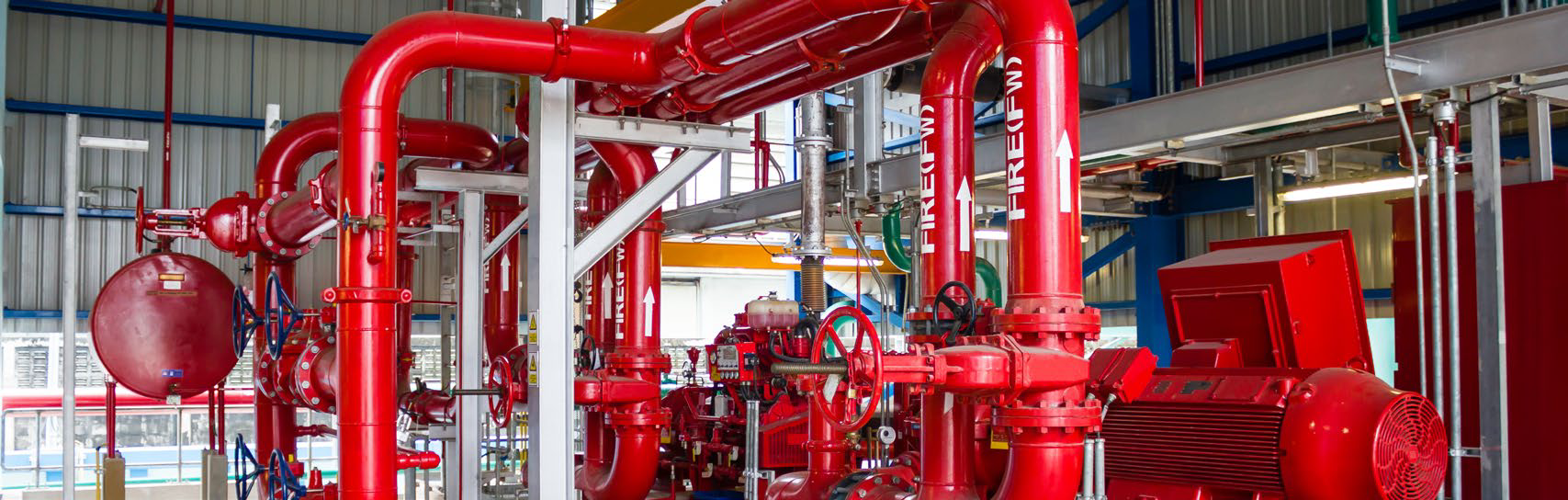
Fire pump room

Assessing Fire Pump Efficiency and Performance

Problem

An electricity and water utility in the Middle East operates 400 substations across four regional zones. To monitor fire pump performance and efficiency against specification, the utility relied on variable-area (VA) and Venturi flow meters installed on the fire pump lines. Readings from the VA meters were unstable, and the accuracy of both meter types was in question. The utility needed an alternative measurement solution that would resolve these issues without costly mechanical modifications to the piping.

Application

MediumRaw water
Pipe sizesVarious
TemperatureAmbient
Panametrics

Benefits:

  • More stable and accurate readings than the utility’s existing permanent meters
  • Clearer picture of fire pump performance — critical for safety
  • Positive results led the customer to order three additional units to equip all four zones
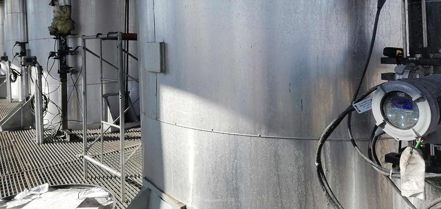
TransPort PT900 clamp-on installation

Solution

Panametrics’ local channel partner ran an on-site demonstration of the portable TransPort PT900 clamp-on flow meter at all four substations, showcasing its accuracy, performance, and ease of use compared with the existing meters. Convinced by the results, the customer purchased a unit in August 2018. It has since been used across multiple substations, consistently matching measured flow with the pumps’ theoretical capacity.

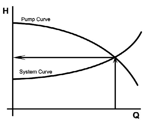
Pump performance curve

Comparing the pump curve with the system curve helped confirm the fire pumps were performing to specification.

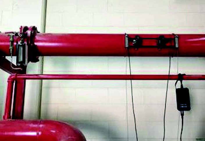
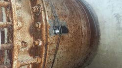
Clamp-on transducer installation
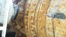
Fire pump room detail

Portable ultrasonic liquid flow meter Panametrics TransPort PT900

Datasheet (PDF) TransPort PT900

Source: Panametrics Application Note (panametrics.com) — © Panametrics LLC. Localized and adapted by INTECH CONTROL, official Panametrics representative in the Slovak Republic and Hungary.
by Bohuslav Bobrik Bohuslav Bobrik

Wastewater Treatment Plant Flow Measurement

APPLICATION NOTE
Wastewater treatment plant aerial view

Wastewater Treatment Plant Flow Measurement

Problem

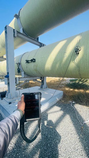
A company in Turkey operates several wastewater treatment facilities in the Istanbul district, mainly using open-channel flow meters at the inlet and outlet. At one facility, flow readings between inlet and outlet were unbalanced by up to 30% — a discrepancy that shouldn’t occur under normal operation. After the open-channel inlet, the pipe runs underground with very limited access for flow measurement, with the only viable access point being the valve room. Most flow meter vendors could not offer a solution, and the wastewater also contained up to 2% solid content by volume.

PipeCarbon steel, diameter 2200 mm (88 in), thickness 12 mm (~½ in)
MediumWaste water, temperature 10 to 20°C (50 to 68°F)
Velocity0 to 2.3 m/s (0 to 7.55 ft/s)

Application

AquaTrans AT600 clamp-on flow meter measures wastewater intake on a large pipe with very tight available space, providing a non-intrusive solution where traditional flow meters could not be installed.

Panametrics

Benefits:

  • Reliable measurement despite tight installation space
  • Handles wastewater with up to 2% solid content
  • Non-intrusive clamp-on installation, no process shutdown
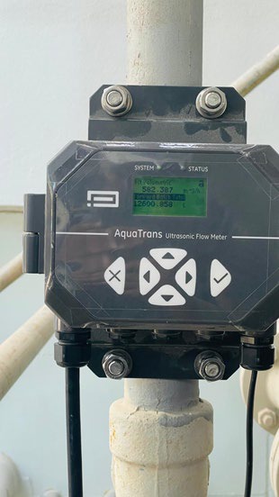
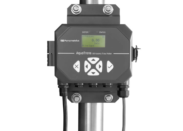
AquaTrans AT600 ultrasonic flow meter

Solution

The Panametrics partner proposed testing the AT600 clamp-on flow meter for this application, despite the short downstream piping run. The meter was installed in a single traverse configuration, as there wasn’t enough available length for a dual-traverse setup. The customer tested the meter for a full month to properly evaluate its performance, and the results matched expectations. As a public company, the customer had to run a formal tender process — two other companies attempted flow measurement at the same location but could not achieve stable readings, with some showing severe fluctuations. As a result, the customer selected the Panametrics AT600 clamp-on flow meter as the reliable solution for this challenging wastewater application.

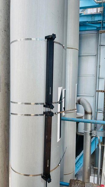
AT600 sensor installation on pipe
AT600 sensor installation close-up detail

Ultrasonic liquid flow meter Panametrics AquaTrans AT600

Datasheet (PDF) AquaTrans AT600

Source: Panametrics Application Note (panametrics.com) — © Panametrics LLC. Localized and adapted by INTECH CONTROL, official Panametrics representative in the Slovak Republic and Hungary.